How and why should I test a cable or wiring loom?


1. You have built the wrong cable.
2. Some connections that should be made are not.
3. Some connections that should not be made are.
4. Some connections that should be made almost are.
5. Some connections that should not be made almost are.
There are many tests that can be applied to a cable. Deciding what are the most appropriate tests for your cable harness or wiring loom is not always obvious. This article provides an overview of the tests that can be applied. It explains how they work and the most appropriate application.


This test requires no equipment other than a good pair of eyes, although a magnifier will help to spot the less obvious faults. Key points to include are:
- Check that correct parts are being used (not just pattern but specified quality level).
- Cable length.
- Wire colour.
- Wire gauge.
- IDC cables are correctly registered.
- Crimps are correctly positioned (ensure that insulation isn't trapped).
- Contact fully into housing.
- Pull test on Crimp.
- Contacts are free of contamination e.g. Flux.
- Loose or broken strands.
It is important that the crimp force of tools is monitored as incorrect pressure can lead to loose crimps (force too low) or broken wire strands (force too high).

This test is normally carried out at a low voltage and current, typically 5 Volts at a few milliamps. The simplest tester is a battery and a buzzer. This is sometimes called ringing out a cable.
For each connected pin in the cable carry out the following.
1. Ensure that it is connected to all the points shown on the drawing.
2. Check against all the other pins to ensure that there are no shorts.
This is repeated for every pin.
This test will find a high proportion of faults, but there are some disadvantages in performing it manually
- You may miss a connection, possibly due to a lapse in attention, an interruption or misreading the drawing.
- If there is an intermittent fault the process of holding on the probes may make the connection.
- Shorts can be missed as the check is ignored for some (or all) of the pins on the assumption that a short is not possible in a particular configuration.
- The process is very slow.
- This process is very expensive.
There are automatic test systems that allow you to carry out the above test in a few seconds. The tests are exhaustive rather than exhausting.
- All connections are checked.
- The cable is checked against a golden sample or a previously stored master.
- The test can be repeated to check for intermittent faults.
- All possible shorts are checked for.
- The test takes little more than the time to connect up the cable.
- The equipment will typically recoup the cost in less than a year. See Save Time and Money
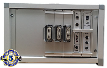
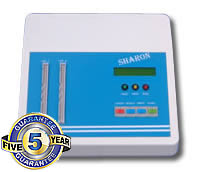
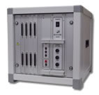
For small standalone test areas a tester like the B801 "Sharon" cable loom tester provides a cost-effective solution. A more comprehensive connection tester is the B857 "Tracy" cable harness and wiring loom tester . Both Testers can use the same interface jigs and connectors so it is easy to mix the two, or to start with the Sharon and invest in the Tracy at a later date.
 |
 |

Levels 1 and 2 will satisfy the majority of customers, but there are occasions when further testing is required. This is normally when failure of the cable is very costly or may cause a safety hazard. Measuring the resistance of the cable would be the preferred next step. The resistance of a cable may vary for a number of reasons.
- Wire outside spec.
- Poor soldered joint.
- Faulty crimp.
- Contamination on contact.
- Contact outside specification.
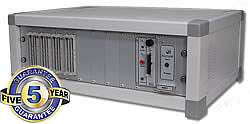
The simple way to measure the resistance of a cable is to use an ohmmeter. This may not be the best solution as the resistance of a cable is typically in the region of an ohm or less. This is similar to the uncertainty of the ohmmeter. This uncertainly is caused by variation in the lead resistance and the resistance of the probes. The better solution is to use a Kevin resistance meter or 4-wire tester. See Measuring Small Resistances for a technical description of how 4 wire testing works. An example is the BA765 "Henry".
You should bear in mind that the resistance of the cable will vary depending on its specification and manufacturer. The resistance will also vary with temperature. A tolerance should be allowed to account for this. Measuring at a constant temperature will make the job easier.
This measurement will add considerably to the confidence in the cable, however manual measurement does take a considerable amount of time. An automatic system such as the BA765 "Henry" cable tester / harness tester will carry out the test in a number of seconds. It is worth considering this system, as there are many advantages over manual measurement.
- All connections are checked.
- The cable is checked against a known spec.
- The test can be repeated to check for intermittent variation.
- The resistance can be stored in an Access database for SPC
- All testing is documented automatically and printed evidence or bar-codes can be used
- There is no chance of the wrong values being used as the part is tested against a part number defined specification.
- The equipment will typically recoup the cost in less than a year. See Appendix A

Damage to the insulation or contamination may not be detected by testing at levels 1 to 3. If the insulation system fails it can be very costly. An IR Test measures the electrical insulation resistance of the system. This is sometimes also called a Mega test. Failure of this test may be due to one or more of the following.
- Damaged insulation
- Contamination by flux or finger residues
- Excessive humidity
This measurement is carried out at a high voltage in order to measure the resistance accurately, however the voltage is not intended to stress the cable. The test would typically be carried out at a voltage in the range 500 to 1000 V although if sensitive components such as capacitors have been fitted for EMC purposes then the test may have to be carried out at a much lower voltage. The tests are usually carried out at DC so that only the resistive current is measured. An AC test would include the capacitance of the cable in the measurement.
The test voltage should be allowed to settle for a short while so that any current due to the cable capacitance being charged can be nulled out. An adjustable dwell time ensures the system has stabilised. Attempting to ignore this will produce unreliable readings.
This measurement will add considerably to the confidence in the cable, however manual measurement does take a considerable amount of time. An automatic system such as the BA765 "Henry" cable harness wiring loom tester will carry out the test faster and will enable the operator to deal with other tasks during the testing period.
It is worth considering this system, as there are many advantages over manual measurement.
- All connections are checked.
- The cable is checked against a known spec.
- All testing is documented automatically and printed evidence or bar-codes can be used
- There is no chance of the wrong values being used as the part is tested against a part number defined specification.
- The equipment will typically recoup the cost in less than a year. See Appendix A
- Automatic testing allows the operator to be protected from high voltages using interlocks. This is an important area of operator safety.

This test is carried out at a high voltage but it differs from the Insulation Resistance test in the following ways.
- The purpose of this test is to stress the insulation so that the insulation breaks down, it is typically carried out at twice the operating voltage plus 1000 volts.
- The current measured in the "Insulation Resistance Test" is the average current after the system has stabilised. In a "Dielectric Strength Test" the peak current is measured so that if flashover occurs then this will be recorded as a failure.
- The test is typically carried out at AC, however if permitted by the specifying authorities the test can be carried out at DC using 1.4 times the voltage.
- This test can detect points that are nearly touching such as wire ends, if flashover occurs this would be logged as a fault. It should be remembered that at the typical test voltage of 1500V DC flashover will only occur if the points have a separation of less than 0.2mm